By close of play last Friday - 2hrs after this photo was taken - the ridge beam and both gable walls were complete. During the couple of days prior to this, by quirk of structural engineering design the first floor boarding was glued and nailed in place, the idea being to provide a strong joint between the 1st floor I-beam joists and the binder plate (a deep beam which runs along the top of the ground floor wall panels against which the ends of the joists are butted).
In my (and our joiner's!) view this was quite an unusual detail, but a call to our stuctural engineer - "just to make sure..." - clarified the thinking behind it. The downside was that the T&G chipboard flooring had to be protected from the weather until the building is made watertight, as being merely 'moisture resistant' isn't exactly a qualification for survivablity for up to a month's battering by the west of Scotland's climate in November!This coming week should see the completon of the 1st floor wall panels and start of work on the roof. On the 'goods inwards' front, the windows are due to be delivered this week and possibly the Pavatherm wood fibre insulating cladding board.
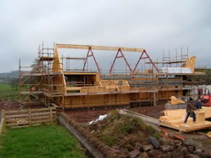
Ridge beams...

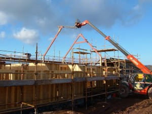
With the three portal frames now in place (which, by the way, fitted perfectly!) the end of last week saw the the central ridge beams lifted in place to tie the portals together at their apex and of course form the centreline of the roof against which will be fixed the rafters.
The ridge beams is made from mltiple bonded laminations of wood ('glu-lam') and is as strong as it looks! It's nice to see the height of the house now and easier to imagine how the 1st floor rooms will look.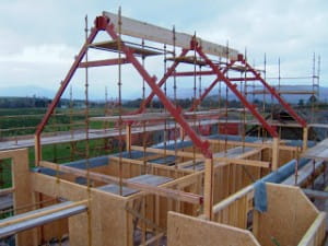
This coming week work will start on installing the first floor joists, 1st floor walls and gables, so things should really start to take shape soon. Last but not least, a letter came though from the Enery Savings Trust at the weekend with the grant offer for the heat pump, which in Scotland is 30% of capaital cost up to a maximum of £4k; every little helps!
Dry stone dyke

With work continuing on the house portal frame, the finishing touches to the dry stone retaining wall are well underway. With the wall having been substantially completed a couple of weeks or so ago using stone from the old (demolished) farmhouse, our friend and expert wall builder came across a source of coping stones from a derelict wall at a nearby farm. No sooner as a price was agreed these hand-cut half-round stones were picked out of the ground and brought the couple of miles to ECF to top off our new wall.
Complete with moss and lichen the 'copes' are well weathered and match perfectly with the old stone from the house. Behind the stone wall is a 150mm dense concrete block wall which will do most of the work, such that the coping stones are laid across the two on a bed of mortar to tie the whole lot together. At the back of this the soil will be cultivated to form a raised bed that will completely hide the concrete blocks as shown in the photo.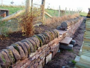
Portal frame arrives
Late afternoon yesterday saw the arrival of the prefabricated portal frames along with the brackets and bits to put them together. These are more than a week overdue and their late arrival has meant a temporary stop on site for a few days as nothing further could be done without them beyond the ground floor panels which are now in place .
However, things moved along again today as our main builder/project manager and two joiners started to the erect this steel framework into the gound floor panels. By the end of the day two of the three frames were in place and secured.
So why a portal frame? Well, this 1.5 storey house is very open plan internally with generous internal room heights (2.7m ground floor, 3.5m kitchen/diner, 2.9m first floor) such that the upper floor ceilings follow the roof line almost to the ridge, with a small loft space around 1.5m high. With this internal design it was tricky to use a (more conventional) truss system, so the portal frame is used to provide torsional stiffness to the building and carry a roof ridge beam, against which rafters will be supported for the roof. In effect, this is a contemporary take on a traditional method of roof construction.
In designing the roof we have also avoided the use of roof purlins (horizontal rafter supports) by using timber 'I-beams', each of which will span around 5m from eaves to ridge at a 45 deg. pitch and carry the weight of the slate roof supported only at either end. This not only keeps the internal structure clean and uncluttered, but their 352mm depth will be fully filled with insulation and their thin shear web minimises thermal bridging. The end result is a stiff, clean, super-insulated roof structure.
The down side to this constrcution has been additional labour/time and ultimately cost, but the end result should be worthwhile.
Wall plates installed
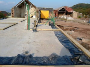
On Tuesday of this week the builders spent the morning fitting the wall plates (also called 'sole plates'). In timber frame construction these set out the plan of the ground floor layout and form the interface between the walls (both external and internal) and the ground floor slab/foundations.
The wall plates comprise timber of the same width dimension of the wall panels they support (ie. 140mm and 89mm), and are simply cut to length and laid on a bed of mortar (and damp proof course at the outside walls).
Whilst an apparently straightforward process, locating the wall plates in the correct positions is critical to the ultimate accuracy of the frame installation.
As an aside, this process also introduced a simple but effective airtightness detail to the building, in that the overhanging damp proof membrane (from under the slab) is folded back over the slab at the edges for later trimming and connection to the vapour membrane to be installed on the inside of the wall panels. Whilst not an essential detail (and usually omitted), this ensures an airtight and flexible linear floor/wall joint that should last through the first few years of the building 'settling' and drying out, a process often responsible for significant degradation of airtighness as cracks open between differing materials (eg wood/mortar) and thus worsening energy efficiency. Polythene membrane, being a flexible material, withstands this movement.
As an aside, airtightness is a key component to low energy building design alongside insulation, the minimisation of thermal bridges, orientation and glazing. Coupled with this it is essential to have an effective ventilation system to ensure good air quality inside - more on this and other airtighness details as the house takes shape.
Search and book
Tags
animals architectural design awards, cottages, sustainability bees caravan cottages Curlew Cottage days out design dogs eastcambusmoon electric vehicles foundation fruit and veg production furniture gold award great review green toursim hard landscaping heat pump heat recovery hens holiday accommodation insulation interiors lambing landscaping loch lomond low energy measures national park nature outings owls people photoshoot roof solar PV timber frame Training ventilation walks website windows
Blog archive
- June 2019 (1 entry)
- February 2019 (1 entry)
- December 2018 (1 entry)
- November 2018 (1 entry)
- April 2018 (1 entry)
- December 2017 (1 entry)
- October 2017 (2 entries)
- June 2017 (1 entry)
- April 2017 (2 entries)
- March 2017 (1 entry)
- February 2017 (1 entry)
- February 2016 (1 entry)
- June 2014 (1 entry)
- June 2013 (1 entry)
- April 2013 (1 entry)
- February 2013 (1 entry)
- May 2012 (2 entries)
- April 2012 (1 entry)
- March 2012 (2 entries)
- December 2011 (1 entry)
- August 2011 (2 entries)
- June 2011 (4 entries)
- May 2011 (4 entries)
- April 2011 (1 entry)
- December 2010 (4 entries)
- October 2010 (2 entries)
- August 2010 (2 entries)
- December 2009 (1 entry)
- November 2009 (2 entries)
- October 2009 (2 entries)
- September 2009 (3 entries)
- August 2009 (1 entry)
- July 2009 (2 entries)
- June 2009 (3 entries)
- May 2009 (7 entries)
- April 2009 (2 entries)
- March 2009 (2 entries)
- February 2009 (1 entry)
- January 2009 (4 entries)
- December 2008 (2 entries)
- November 2008 (1 entry)
- June 2008 (5 entries)
- May 2008 (4 entries)
- April 2008 (11 entries)
- March 2008 (14 entries)
- February 2008 (9 entries)
- January 2008 (12 entries)
- December 2007 (11 entries)
- November 2007 (11 entries)
- October 2007 (10 entries)
- September 2007 (6 entries)
